
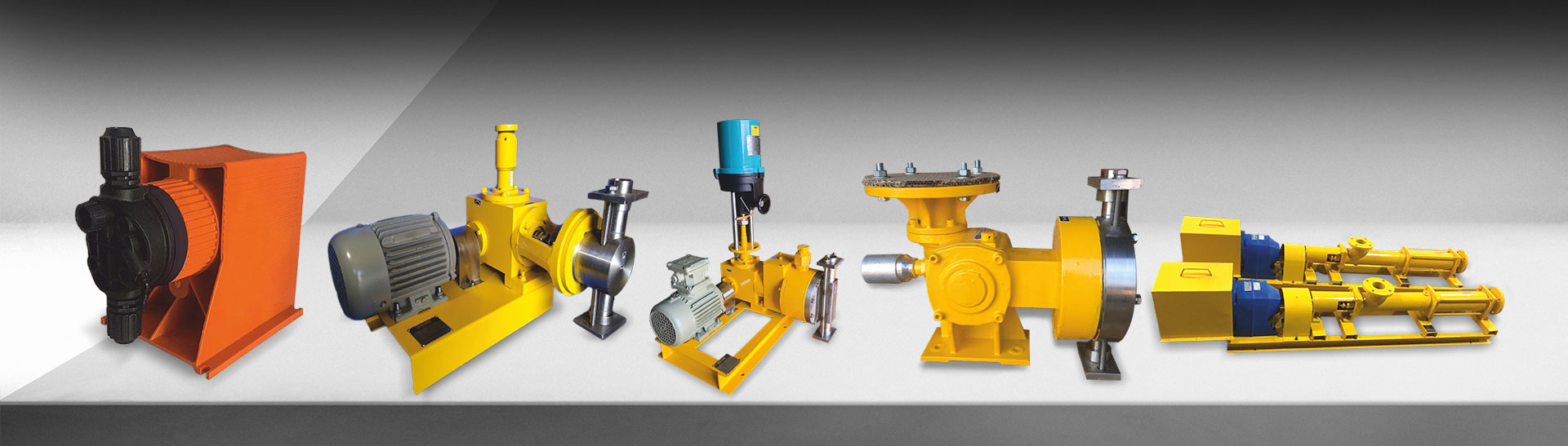
Dosing pumps are essential components in industries such as chemical processing, water treatment, pharmaceutical production, and food manufacturing. A dosing pump delivers precise, repeatable volumes of liquid into a process stream. 7 main types are available. Each type suits different pressures, flow rates, and liquid properties.
What is a Dosing Pump?
A dosing pump is a positive displacement pump designed to deliver precise, repeatable volumes of liquid into a process stream. Unlike transfer pumps, which prioritize bulk flow, dosing pumps focus on accuracy, repeatability, and chemical compatibility. They are typically used for chemical injection, pH correction, disinfection, and proportioning applications.
What Is a Dosing Pump?
A dosing pump is a positive displacement pump designed for accuracy, repeatability, and chemical compatibility. It differs from transfer pumps, which focus on bulk flow.
Dosing pumps apply to chemical injection, pH correction, disinfection (DIS), and proportioning applications. The term metering pump (MP) is used interchangeably. “Metering” emphasizes precision and calibration. Both terms refer to controlled-volume liquid delivery.
7 Types of Dosing Pumps
The 7 main types differ in operation, pressure range, flow capacity, and suitable liquid characteristics.
1. Electronic Metering Pump
Electronic metering pumps use a stepper motor or solenoid to drive a diaphragm or plunger. This mechanism gives precise flow rate control.
Electronic metering pumps support low- to medium-flow dosing. Flow ranges from 1 ml/h to 80 L/h. Maximum pressure reaches 25 bar.
These pumps offer 3 control options: pulse input, 4–20 mA analog, and manual stroke-frequency adjustment. They integrate easily with automation systems.
Common applications include 3 use cases:
- Boiler water treatment (hydrazine, ammonia)
- Cooling tower chemical dosing
- Reverse osmosis (RO) antiscalant dosing
Key limitation: electronic metering pumps are sensitive to power supply fluctuations and require regular calibration.
2. Plunger Pump
Plunger pumps use a reciprocating plunger that draws in and discharges liquid, creating a pulsating flow.
Plunger pumps handle high-pressure applications. Pressure reaches up to 400 bar. This makes plunger pumps suitable where exact discharge per stroke is critical.
These pumps comply with API 675 standards. API 675 ensures repeatability of ±1% and defined accuracy. Industries using plunger pumps include oil & gas, petrochemical, and fertilizer production.
Key limitation: packing wear requires periodic tightening or replacement, increasing maintenance effort.
3. Hydraulically Operated Diaphragm Pump
Hydraulically operated diaphragm pumps use a hydraulic cylinder to drive a diaphragm, displacing the liquid.
These pumps combine the precision of plunger pumps with leak-free diaphragm operation. Hydraulic fluid ensures uniform diaphragm motion, extending service life.
Flow ranges reach up to 500 L/h. Pressure capability extends to 400–500 bar.
Applications include 4 process types:
- Acid dosing
- Polymer injection
- Power plant chemical treatment
- Refinery processes
Key limitation: these pumps require a separate hydraulic power source and are more complex to maintain.
4. Mechanically Actuated Diaphragm Pump
Mechanically actuated diaphragm pumps use a mechanical linkage to drive a diaphragm, similar to a reciprocating pump.
These pumps offer a simple, reliable design. Flow rates range from 5 L/h to 200 L/h. Maximum pressure reaches 10 bar.
They are preferred for 3 common uses:
- Medium-pressure water treatment
- Effluent treatment plant (ETP) chemical dosing
- General-purpose chemical neutralization
Maintenance is minimal. Diaphragm replacement occurs every 6–12 months depending on duty cycle. Valve cleaning is the other primary task.
5. Progressive Cavity (Screw) Pump
Progressive cavity pumps use a rotating screw that meshes with a stationary stator, creating a progressive cavity that moves the liquid.
These pumps deliver non-pulsating flow and gentle shear. They handle viscosities up to 50,000 cP. Flow and speed have excellent linearity.
Common applications include 4 fluid types:
- Polymer dosing
- Molasses and food-grade viscous liquids
- Slurries and abrasive materials
- Viscous emulsions in paints and chemicals
Key limitation: progressive cavity pumps are more expensive than diaphragm types and may have lower flow rates at high pressures. Maintenance involves rotor-stator inspection and periodic lubrication.
6. Peristaltic (Tube) Pump
Peristaltic pumps use rotating rollers that compress a flexible tube, pushing liquid through while preventing backflow.
These pumps are self-priming. They handle slurries, outgassing liquids, and chemically aggressive fluids. The flexible tube isolates liquid from all mechanical components, producing contamination-free operation.
Flow ranges from 0.1 to 100 L/h. Pressure reaches up to 8 bar.
Applications cover 4 chemical types:
- Sodium hypochlorite dosing
- Ferric chloride and polymer dosing
- pH correction in wastewater treatment
- Disinfection in pharmaceutical and food production
Key limitation: tube wear limits continuous-duty operation. Tubes last 500–1,000 hours depending on pressure and chemical compatibility.
7. Gear Dosing Pump
Gear dosing pumps use 2 intermeshing gears that trap and transport fluid between the teeth and casing.
These pumps deliver smooth, pulse-free flow. They have a compact design. Flow ranges from 0.5 to 150 L/h. Pressure reaches 15–20 bar.
Gear dosing pumps are ideal for 3 fluid types:
- Lubricants and fuels
- Polymers and additive injection
- Oils in continuous lubrication processes
Key limitation: gear pumps are not suitable for abrasive or particulate-laden fluids. Internal leakage at low viscosities reduces accuracy.
5 Factors to Consider When Choosing a Dosing Pump
5 primary factors determine which pump suits a given application.
- Liquid properties: assess viscosity, abrasiveness, corrosiveness, and temperature.
- Flow rate and pressure: match pump capacity to the process requirements.
- Accuracy and precision: define the acceptable dosing tolerance for the application.
- Maintenance requirements: evaluate frequency of diaphragm replacement, valve cleaning, and calibration.
- Cost: calculate both initial purchase price and ongoing operating costs.
Advanced Selection Parameters
Engineers evaluate 6 additional parameters beyond the primary 5 factors.
| Parameter | Why It Matters | Typical Range |
|---|---|---|
| Turndown Ratio | Determines flow adjustability; higher ratio = finer control | 10:1 to 1000:1 |
| Accuracy / Repeatability | Impacts chemical efficiency and process consistency | ±1% (API 675) |
| Control Type | Defines integration capability | Manual, pulse, 4–20 mA, Profibus/Modbus |
| Material Compatibility | Prevents corrosion and chemical swelling | PP, PVDF, SS316, PTFE, EPDM, FKM |
| Viscosity Handling | Impacts suction and discharge performance | Up to 50,000 cP (PC, peristaltic) |
| Duty Cycle | Distinguishes continuous from batch dosing | Depends on process type |
Installation and Piping Essentials
Proper piping ensures dosing accuracy and pump longevity. Follow this 6-point checklist:
- Keep suction lines short and straight.
- Use foot valves, strainers, and non-return valves.
- Install back-pressure valves and anti-siphon valves on the discharge side.
- Add pulsation dampeners for plunger or diaphragm pump types.
- Include calibration columns for flow verification.
- Vent lines adequately to avoid air pockets, particularly for outgassing liquids.
Typical Applications by Pump Type
| Pump Type | Common Applications | Industry Examples |
|---|---|---|
| Electronic / Solenoid Diaphragm | pH correction, boiler feedwater, RO dosing | Water Treatment, Cooling Towers |
| Plunger | High-pressure additive injection | Petrochemical, Fertilizer |
| Hydraulic Diaphragm | Corrosive acid dosing | Power Plants, Refineries |
| Mechanical Diaphragm | Effluent treatment, neutralization | ETPs, Food Industry |
| Progressive Cavity | Polymer, viscous slurry dosing | Paints, Food, Chemicals |
| Peristaltic | Hypochlorite, polymer, slurry dosing | Water & Wastewater, Pharma |
| Gear | Oils, fuels, lubricants | Lubrication, Chemical Processing |
Standards and Compliance
API 675 is the primary standard for industrial metering pumps. API 675 defines 4 key performance requirements:
- ±1% steady-state accuracy
- ±3% repeatability
- Leak-free performance
- Defined net positive suction head (NPSH) and mechanical stroke integrity
Hydraulic and plunger pump types are typically built to this specification for use in regulated industries.
Conclusion
Selecting the right dosing pump depends on your specific application requirements. By carefully considering the factors discussed above, you can choose a pump that meets your needs for accuracy, reliability, and efficiency.
Consulting with a dosing pump specialist like Verito Engineering Pvt Ltd can also provide valuable guidance and recommendations.
Verito’s portfolio includes solenoid, plunger, mechanical & hydraulic diaphragm, and progressive cavity dosing pumps — engineered for precision, durability, and process efficiency across India’s water, chemical, and process industries.
Common FAQs
Q1. Are metering and dosing pumps the same?
Mostly yes. “Metering” emphasizes precision and stepless adjustability. “Dosing” emphasizes quantity control. Both terms refer to the same pump category.
Q2. Which pump is best for viscous or abrasive fluids?
Progressive cavity and peristaltic pumps are best for viscous, shear-sensitive, or abrasive fluids. Both handle up to 50,000 cP viscosity.
Q3. What is API 675, and why does it matter?
API 675 defines performance, accuracy, and testing requirements for controlled-volume metering pumps. It ensures reliability in critical process industries.
Q4. What is the typical lifespan of a diaphragm or peristaltic tube?
Diaphragm lifespan ranges from 6 to 18 months depending on duty cycle. Peristaltic tubes last 500 to 1,000 hours depending on pressure and chemical compatibility.
Q5. How do I size a dosing pump for my application?
Multiply the required chemical flow by a safety factor of 1.1 to 1.25. Then match the result with operating pressure, material compatibility, and the desired turndown ratio.